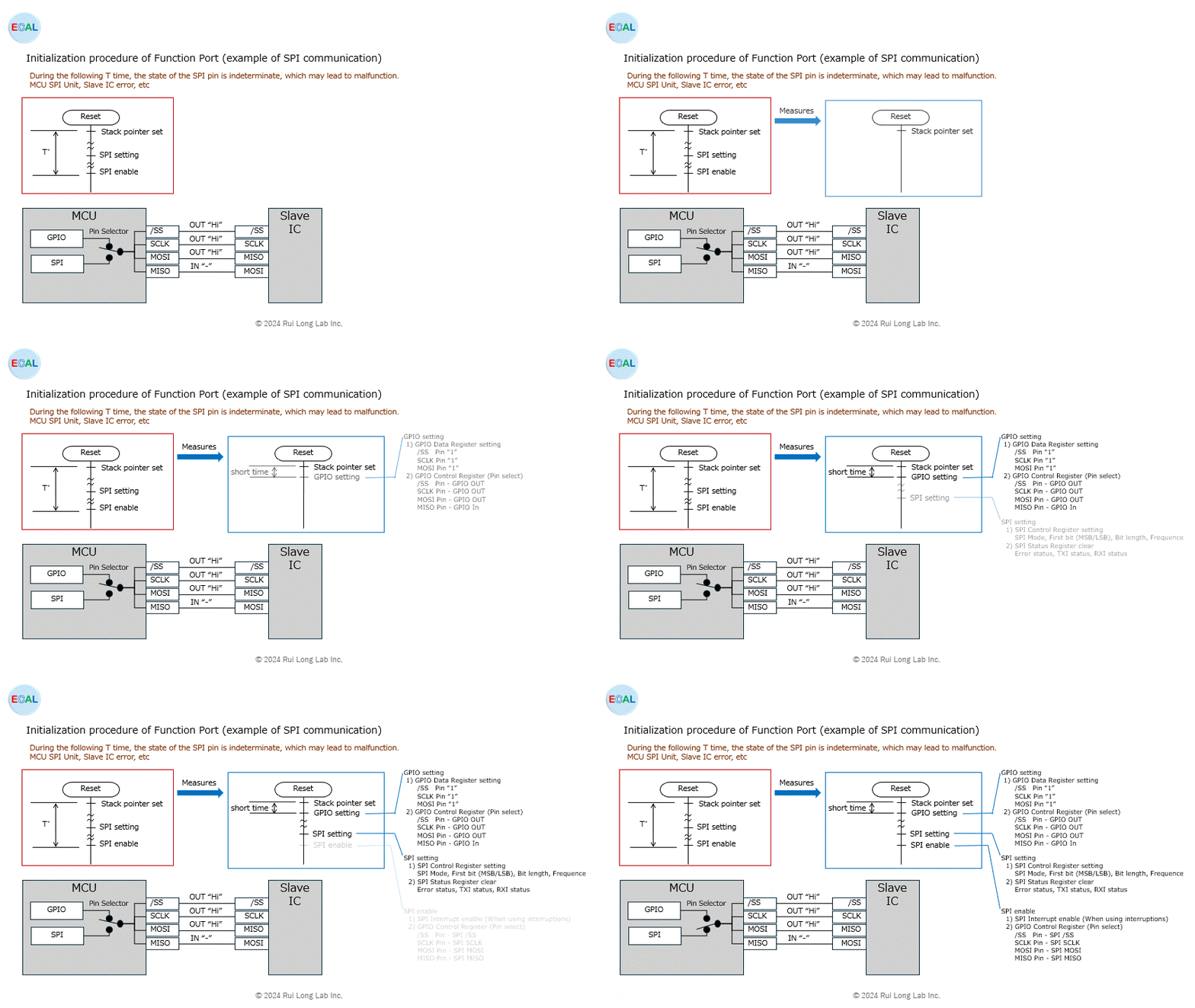
This posting describes the procedure for initializing the functional ports.
Functional ports often need time to adjust to hardware requirements during initialization, which can cause malfunctions. To avoid this, the following procedure is recommended for initializing functional ports.
| 1. GPIO setting | 1) GPIO Data Register setting | /SS Pin “1” SCLK Pin “1” MOSI Pin “1” |
| 2) GPIO Control Register (Pin select) | Pin function selection /SS Pin – GPIO OUT SCLK Pin – GPIO OUT MOSI Pin – GPIO OUT MISO Pin – GPIO In | |
| 2. SPI setting | 1) SPI Control Register setting | SPI Mode First bit (MSB/LSB) Bit length Frequence |
| 2) SPI Status Register clear | Error status TXI status RXI status | |
| 3 SPI enable | 1) SPI Interrupt enable | When using interruptions |
| 2) GPIO Control Register (Pin select) | Pin function selection /SS Pin – SPI /SS SCLK Pin – SPI SCLK MOSI Pin – SPI MOSI MISO Pin – SPI MISO |

