Refer to the following example to see how to incorporate several of the same electronic components in a user program.
Exe :
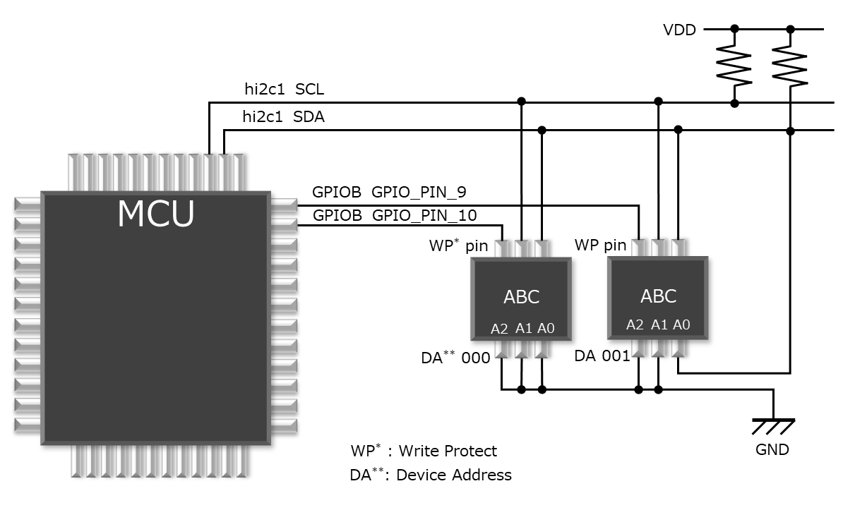
Two electronic components ABC Memory (I2C type), HAL STM32CubeF4

Step1 Add two ABC codes to “oss_ecal.h”
Make the following settings in “oss_ecal.h” (Ver 01.01.00 or later).
1. Added Components number codes eABC_1, eABC_2.
The API function argument etCMP should be used to select electronic components using this code eABC_1, eABC_2, not eABC.
// Components number codes      1 to 49999
typedef enum
{
// ADC components 1 to 19999
        eAD22100A               = 1U    ,       // Analog devices AD22100A
        eAD22100K               = 2U    ,       // Analog devices AD22100K
        eAD22100S               = 3U    ,       // Analog devices AD22100S
        eAD22103K               = 4U    ,       // Analog devices AD22103K
        eBD1020HFV              = 5U    ,       // ROHM BD1020HFV
        eCHS_MSS                = 6U    ,       // TDK CHS-MSS
        eCHS                    = 7U    ,       // TDK CHS-UPS, CHS-UPR, CHS-UGS, CHS-UGR
        eGP2Y0A21YK0F           = 8U    ,       // SHARP GP2Y0A21YK0F
        eGP2Y0A41SK0F           = 9U    ,       // SHARP GP2Y0A41SK0F
        eGP2Y0A51SK0F           = 10U   ,       // SHARP GP2Y0A51SK0F
        eLM35                   = 11U   ,       // Texas Instruments LM35, LM35A
        eLM35C                  = 12U   ,       // Texas Instruments LM35C, LM35CA
        eLM35D                  = 13U   ,       // Texas Instruments LM35D
        eLM45B                  = 14U   ,       // Texas Instruments LM45B, LM45C
        eLM50B                  = 15U   ,       // Texas Instruments LM50B
        eLM50C                  = 16U   ,       // Texas Instruments LM50C
        eTMP9A00                = 17U   ,       // Texas Instruments TMP9A00-EP
        eMAX6605                = 18U   ,       // Maxim Integrated MAX6605MXK+T, MAX6605MXK-T
        eMAX6605V               = 19U   ,       // Maxim Integrated MAX6605MXK/V+T
        eMAX6607_8              = 20U   ,       // Maxim Integrated MAX6607IXK-T, MAX6608IUK-T
        eMAX6613                = 21U   ,       // Maxim Integrated MAX6613MXK+T, MAX6613MXK/V+T
        eMPX4250A               = 22U   ,       // NXP MPX4250A, MPXA4250A
        eMPX5999D               = 23U   ,       // NXP MPX5999D
        eMPXH6115A              = 24U   ,       // NXP MPXH6115A
        eMPXHZ6250A             = 25U   ,       // NXP MPXHZ6250A
        eMPXH6400A              = 26U   ,       // NXP MPXH6400A
        eMCP9700                = 27U   ,       // Microchip Technology MCP9700, MCP9700A
        eMCP9701                = 28U   ,       // Microchip Technology MCP9701, MCP9701A
        eTC1046                 = 29U   ,       // Microchip Technology TC1046
        eTC1047                 = 30U   ,       // Microchip Technology TC1047, TC1047A
        eS58LM20A               = 31U   ,       // ABLIC S-58LM20A
        eS5813A                 = 32U   ,       // ABLIC S-5813A, S-5814A
        eS8110C                 = 33U   ,       // ABLIC S-8110C, S-8120C
        eSTLM20DD9F             = 34U   ,       // STMicroelectronics STLM20DD9F
        eSTLM20W87F             = 35U   ,       // STMicroelectronics STLM20W87F
// I2C components 20000 to 39999
        eS35710                 = 20000U,       // ABLIC S35710
        eHDC1080                = 20001U,       // Texas Instruments HDC1080
        eHS300X                 = 20002U,       // Renesas HS3001, HS3003   [01.01.00]
        eMB85RC256V             = 20003U,       // Fujitsu MB85RC256V       [01.02.00]

        eABC                    = 20004U,       // XYZ ABC [01.03.00]
// SPI components 40000 to 49998
        eMAX6675                = 40000U,       // Maxim Integrated MAX6675
// User setting number 49900 to 49998           // User setting number Add [01.02.00]
        eABC_1                  = 49900U,       // XYZ ABC Device Address 000 [user modification]
        eABC_2                  = 49901U,       // XYZ ABC Device Address 001 [user modification]
// Non component number
        eNON_CMP                = 49999U        // Non component number
}etCMP;
Step2 ABC settings in “user_setting.h”
Make the following settings in “user_setting.h”.
1. Set Device Address ABC_1, ABC_2.
2. Set GPIO CMP_GPIO_NUM, GPIO_ABC_1_WP, PIN_ABC_1_WP, GPIO_ABC_2_WP, PIN_ABC_2_WP for Write Protect.
3. Set I2C CMP_I2C_NUM, I2C_HZ, I2C_ABC, I2C_RETRY.
// Components common setting
//~~~~~~~~~~~~~~~~~~~~~~~~~~~~~~~~~~~~~~~~~~~~~~~~~~~~~~~~~~~~~~~~~~~~~~~~~~~~~~
// Device address Code bit2:A2, bit1:A1, bit0:A0
#define ABC_1                   0b00000000 // A2(bit2)=0, A1(bit1)=0, A0(bit0)=0
#define ABC_2                   0b00000001 // A2(bit2)=0, A1(bit1)=0, A0(bit0)=1

// I2C components address
#define iABC_DEVICE_CODE        0b00001010      // Device common code
#define I2C_ADR_ABC_1           (( iABC_DEVICE_CODE << 3 ) | ( 0x07 & ABC_1 ))
#define I2C_ADR_ABC_2           (( iABC_DEVICE_CODE << 3 ) | ( 0x07 & ABC_2 ))

// Hardware setting by user
//~~~~~~~~~~~~~~~~~~~~~~~~~~~~~~~~~~~~~~~~~~~~~~~~~~~~~~~~~~~~~~~~~~~~~~~~~~~~~~
// OSS-ECAL GPIO hard wiring
#define CMP_GPIO_NUM            2U      // OSS-ECAL GPIO components number
#define GPIO_ABC_1_WP           GPIOB   // ABC WP : MCU Digital Out Port( GPIOB : Generated by configuration )
#define PIN_ABC_1_WP            GPIO_PIN_9  // ABC_1 WP : MCU Digital Out Pin( GPIO_PIN_9 : Generated by configuration )
#define GPIO_ABC_2_WP           GPIOB   // ABC WP : MCU Digital Out Port( GPIOA : Generated by configuration )
#define PIN_ABC_2_WP            GPIO_PIN_10 // ABC_2 WP : MCU Digital Out Pin( GPIO_PIN_10 : Generated by configuration )

// OSS-ECAL ADC components hard wiring

// OSS-ECAL SPI components hard wiring

// OSS-ECAL I2C components hard wiring
#define CMP_I2C_NUM             2U      // OSS-ECAL I2C components number
#define I2C_HZ                  400000  // MCU I2C frequency
#define I2C_ABC                 hi2c1   // I2C Handle( hi2c1 : Generated by configuration )

// OSS-ECAL Wake-up components hard wiring


// Communication setting by user
//~~~~~~~~~~~~~~~~~~~~~~~~~~~~~~~~~~~~~~~~~~~~~~~~~~~~~~~~~~~~~~~~~~~~~~~~~~~~~~
// I2C settings
#define I2C_RETRY               3U      // Retry times
Step3 ABC settings in “user_setting.c”
Make the following settings in “user_setting.c”.
1. Set ABC_1 and ABC_2 to tblGPIO
2. Set ABC_1 and ABC_2 in tblI2C
const stGPIO_STM32_OBJ tblGPIO[ CMP_GPIO_NUM ] =
{
        { eABC_1   , GPIO_ABC_1_WP        , PIN_ABC_1_WP         },

        { eABC_2   , GPIO_ABC_2_WP        , PIN_ABC_2_WP         }
};

// HAL I2C object table for components
const stI2C_STM32_OBJ tblI2C[ CMP_I2C_NUM ] =
{
        { eABC_1   , (I2C_ADR_ABC_1 << 1U)    , &I2C_ABC       },
        { eABC_2   , (I2C_ADR_ABC_2 << 1U)    , &I2C_ABC       }
};