This post describes the impact of an IC communication failure on SPI and I2C communications.
SPI and I2C communications are often used between microcontrollers and peripheral ICs in embedded products. The following is a brief introduction to SPI and I2C communications. For more details, please refer to the separate study.
| Item | SPI(Quad SPI is not included) | I2C |
|---|---|---|
| Communication method | Synchronous Serial Communications Full duplex | Synchronous Serial Communications Half duplex |
| Communication line | SCLK (Clock) MOSI (Master-Out、Slave-In Data) MISO (Master-In、Slave-Out Data) SS (Slave Select) | SCL (Clock) SDA (Data) |
| Communication sequence | 1. SS “Low” output from Master. 2. SCLK output from Master. 3. MOSI(Data) output synchronized with SCLK for Master. 4. MISO(Data) output synchronized with SCLK for Slave. | 1.SDA((Slave address or data)) output from Master. 2. SCL output immediately after SDA output for Master. 3. Slave is SDA output (ACK and data) in line with Master’s SDA. |
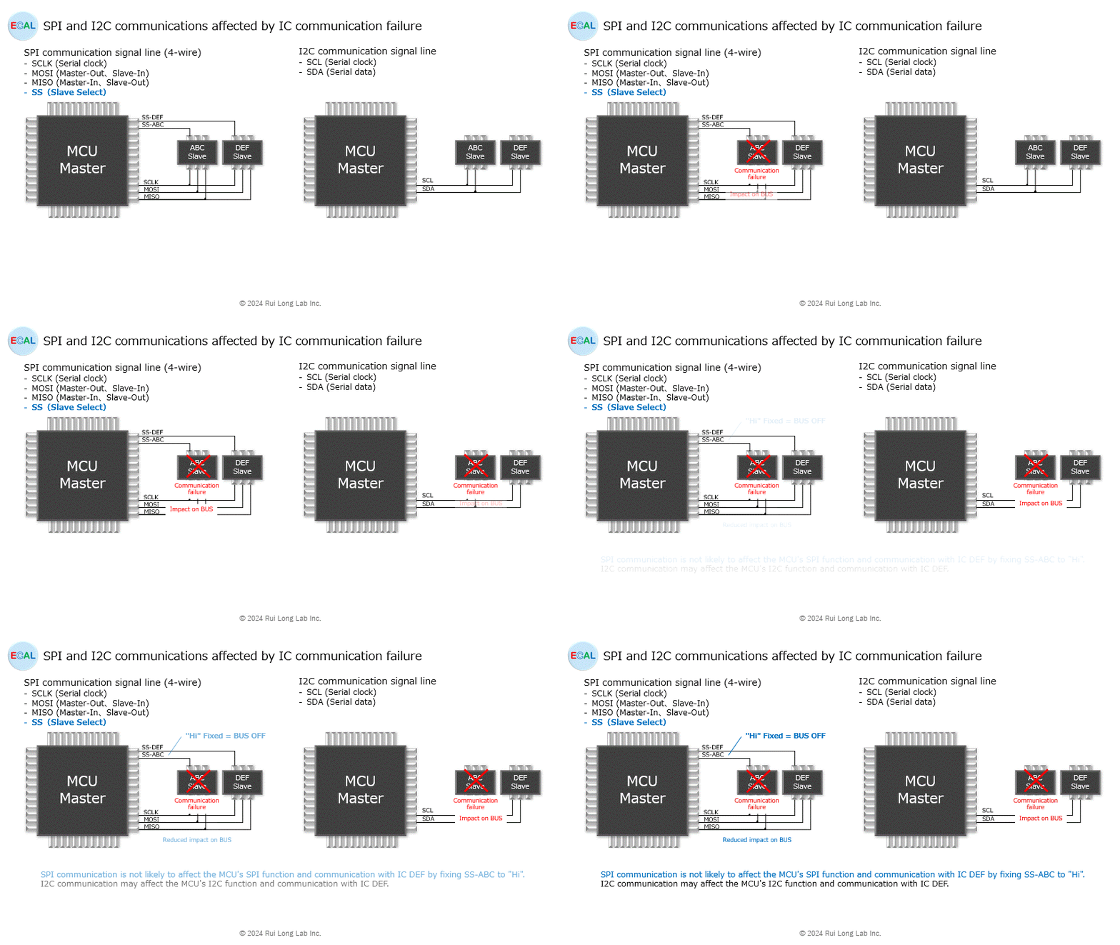
As shown in the figure, suppose that in SPI and I2C communications, the master is a microcontroller (MCU) and IC ABC and IC DEF are connected as slaves.
The effects on SPI and I2C communications in the event of a failure of the communication function of the IC ABC are as follows.
SPI communication:
By fixing SS-ABC to “Hi” in the event of IC ABC failure, IC ABC can be bus-off to minimize the impact on the MCU’s SPI function and communication with IC DEF.
I2C communication:
Failure of the IC ABC may affect the I2C function of the MCU and its communication with the IC DEF.

